DRK124C–Respiratory Mechanical Strength Vibration Tester Operation Manual

Short Description:
Content Chapter 1 Overview 1. Product introduction 2. Technical parameters 3. Adaptation criteria 4. Attached accessories 5. Safety signs, packaging and transportation Chapter II installation and commissioning 1. Safety criteria 2. Installation conditions 3. Installation Chapter 3 test operation 1. Equipment calibration 2. Test environment 3. Test preparation 4. Operation steps 5. Result judgment 6. Precautions Chapter IV repair and maintenance 1. Regular maintenance items 2. After sales serv...
Content
Chapter 1 Overview
1. Product introduction
2. Technical parameters
3. Adaptation criteria
4. Attached accessories
5. Safety signs, packaging and transportation
Chapter II installation and commissioning
1. Safety criteria
2. Installation conditions
3. Installation
Chapter 3 test operation
1. Equipment calibration
2. Test environment
3. Test preparation
4. Operation steps
5. Result judgment
6. Precautions
Chapter IV repair and maintenance
1. Regular maintenance items
2. After sales service
Chapter 1 Overview
1. Product introduction
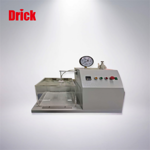
The filter element vibration tester of respirator is designed and manufactured according to relevant standards. It is mainly used for vibration mechanical strength pretreatment of replaceable filter element.
2. Technical parameters
Working power supply: 220 V, 50 Hz, 50 W
Vibration amplitude: 20 mm
Vibration frequency: 100 ± 5 times / min
Vibration time: 0-99min, settable, standard time 20min
Test sample: up to 40 words
Package size (L * w * h mm): 700 * 700 * 1150
3. Adaptation criteria
26en149 et al
4. Attached accessories
One electric control console and one power line.
See packing list for others
1.Safety signs, packaging and transportation
5.1 safety signs  safety warnings
5.2 packaging


Do not put in layers, handle with care, waterproof, upward
5.3 transportation
In the state of transportation or storage packaging, the equipment must be able to be stored for less than 15 weeks under the following environmental conditions.
Ambient temperature range: - 20 ~ + 60 ℃.
Chapter II installation and commissioning
1. Safety criteria
1.1 before installing, repairing and maintaining the equipment, the installation technicians and operators must read the operation manual carefully.
1.2 before using the equipment, operators must carefully read gb2626 and be familiar with the relevant provisions of the standard.
1.3 the equipment must be installed, maintained and used by specially responsible personnel according to the operation instructions. If the equipment is damaged due to incorrect operation, it is no longer within the scope of warranty.
2. Installation conditions
Ambient temperature: (21 ± 5) ℃ (if the ambient temperature is too high, it will accelerate the aging of electronic components of the equipment, reduce the service life of the machine, and affect the experimental effect.)
Environmental humidity: (50 ± 30)% (if the humidity is too high, the leakage will easily burn the machine and cause personal injury)
3. Installation
3.1 mechanical installation
Remove the outer packing box, carefully read the instruction manual and check whether the machine accessories are complete and in good condition according to the contents of the packing list.
3.2 electrical installation
Install power box or circuit breaker near the equipment.
In order to ensure the safety of personnel and equipment, the power supply must have reliable grounding wire.
Note: the installation and connection of power supply must be carried out by professional electrical engineer.
Chapter III test operation
1. Equipment calibration
In principle, the equipment needs to be calibrated once a year. Specific calibration can be entrusted to metrology institute or contact us.
2. Test environment
Temperature: 20 ± 5 ℃, humidity: 50 ± 30%.
Please be sure to keep the temperature and humidity, otherwise it will affect the accuracy of the test.
3. Test preparation
Several replaceable filter elements.
4. Operation steps
4.1. Connect the power supply and turn on the power switch.
4.2. Put the test sample into the test box, and only one sample is allowed to be placed in each small cell, and six samples can be placed at most.
4.3. Set the vibration time to 20s.
4.4. Press the start button to start the vibration and start to vibrate at a certain speed.
4.5. After 20 minutes, the vibration will stop automatically.
4.6. When the time is up, take out the sample and conduct subsequent detection.
4.7. Vibration is a pretreatment test item.
4.8. If it is necessary to test again, please follow the steps. If not, please turn off the power supply and carry out equipment maintenance.
5. Result judgment
Vibration is only a pretreatment item of relevant tests, and there is no final test data.
6. Precautions
6.1. It is forbidden to touch the equipment after vibration is started.
6.2. Although the vibration is cushioned, the vibration may make a loud noise, so it is recommended that the test room be large enough.
6.3. Before each test, check the support between the vibration box and the bottom support plate. Replace it in time if necessary.
6.4. In case of emergency, please cut off the power immediately and conduct the test again after finding out the cause.
Chapter IV repair and maintenance
1. Regular maintenance items
The maintenance cycle depends on the frequency of equipment use and the physical life of equipment components. The following is the component maintenance cycle table.
|
Parts |
Annual inspection |
Replace as needed |
Replace every 1 years |
Replace every 2 years |
|
Vibrating box |
● |
● |
|
|
|
Timer |
● |
● |
|
|
|
Cushion |
● |
● |
|
|
2. After sales service
When you have any abnormality or difficulty in using, please contact the manufacturer or local dealer and provide them with the following information:
2.1 describe the phenomenon of the problem or fault.
2.2 instrument model and factory number
2.3. Product purchase date
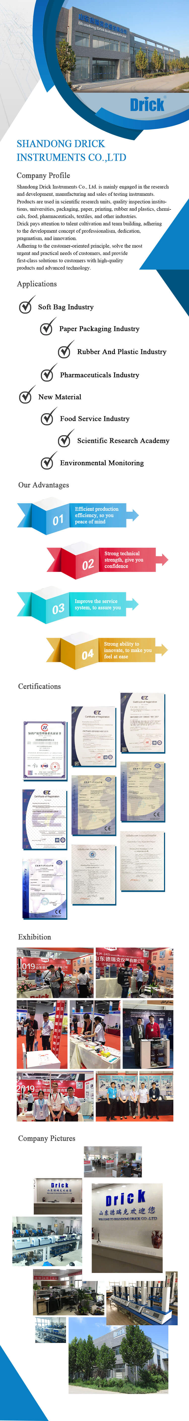
SHANDONG DRICK INSTRUMENTS CO.,LTD
Company Profile
Shandong Drick Instruments Co., Ltd, is mainly engaged in the research and development, manufacturing and sales of testing instruments.
The company established in 2004.
Products are used in scientific research units, quality inspection institutions, universities, packaging, paper, printing, rubber and plastics, chemicals, food, pharmaceuticals, textiles, and other industries.
Drick pays attention to talent cultivation and team building, adhering to the development concept of professionalism, dedication.pragmatism, and innovation.
Adhering to the customer-oriented principle, solve the most urgent and practical needs of customers, and provide first-class solutions to customers with high-quality products and advanced technology.