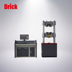
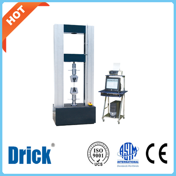
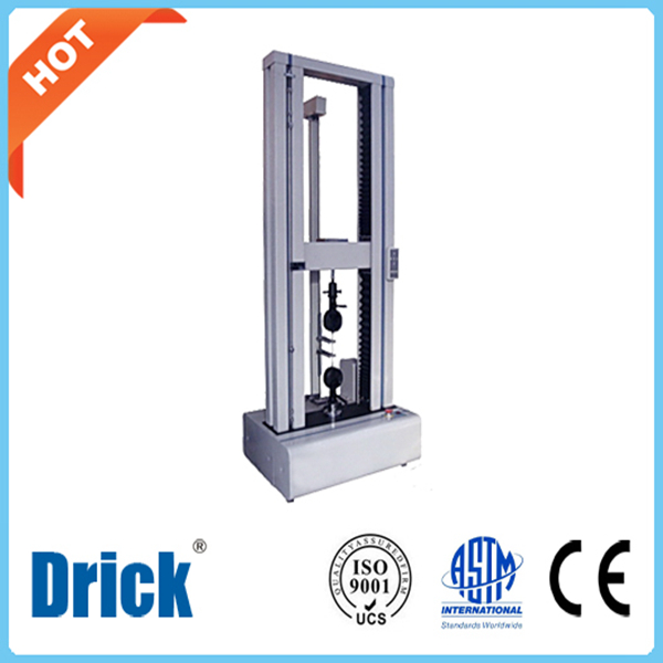
Hydraulic Universal Testing Machine WAW-600D Microcomputer Controlled
Short Description:
WAW-600D Microcomputer Controlled Hydraulic Universal Testing Machine Product Overview: The main body of the WAW-600D microcomputer controlled electro-hydraulic servo hydraulic universal testing machine adopts a cylinder down type main body structure, mainly used for mechanical performance tests such as tension, compression, bending of metal materials, non-metal materials, product parts, components, structural components, and standard parts. If equipped with environmental devices, this serie...
WAW-600D Microcomputer Controlled Hydraulic Universal Testing Machine
Product Overview:
The main body of the WAW-600D microcomputer controlled electro-hydraulic servo hydraulic universal testing machine adopts a cylinder down type main body structure, mainly used for mechanical performance tests such as tension, compression, bending of metal materials, non-metal materials, product parts, components, structural components, and standard parts.
If equipped with environmental devices, this series of testing machines can also perform material tensile, compression, and bending tests in that environment. For example: high temperature tensile, low temperature tensile, compression and other tests.
Suitable for steel, metallurgy, building materials, quality inspection centers, water conservancy and hydropower, highway bridges, research institutes, mechanical engineering in colleges and universities, and other factories, mines, enterprises, and testing and research institutions.
Manufacturing and inspection standards for products
GB2611 “General Technical Requirements for Testing Machines”
JJG139 “Tensile, Pressure, and Universal Testing Machine“
Applicable test method standards
The experimental operation and data processing meet the requirements of hundreds of standards such as GB/T228 “Tensile Test Method for Metallic Materials at Room Temperature”, GB/T7314 “Compression Test Method for Metallic Materials at Room Temperature”, GB/T232 “Bending Test Method for Metallic Materials”, etc. And data processing methods that meet different standards can be configured according to customer needs.
Main technical indicators
1 Host
The main engine adopts a bottom mounted oil cylinder type, with the stretching space located above the main engine, and the compression and bending test space located between the lower crossbeam of the main engine and the worktable.
2 Transmission System
The lifting of the middle crossbeam adopts a motor driven by a chain wheel to rotate the screw, adjusting the spatial position of the middle crossbeam and achieving the adjustment of tension and compression space.
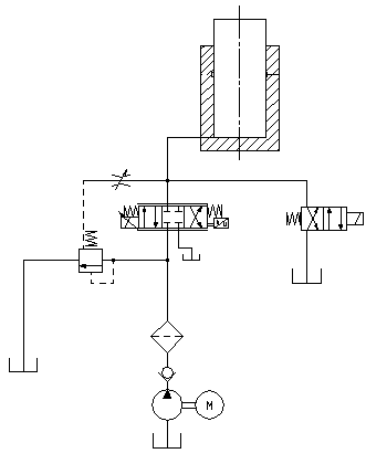
The hydraulic principle of the hydraulic system is shown in Figure 2, which is a load adaptive oil inlet throttling speed control system.
Figure 2 Hydraulic schematic diagram
The hydraulic oil in the oil tank is driven by the motor to enter the oil circuit, and flows through the one-way valve, high-pressure oil filter, differential pressure valve group, servo valve, and enters the oil cylinder. The computer sends control signals to the proportional servo valve to control the opening and direction of the proportional servo valve, thereby controlling the flow into the oil cylinder and achieving control of constant speed test force, constant speed displacement, etc.
4. Electrical measurement and control system:
(1) The core components of the servo control oil source are all imported original components with stable performance.
(2) It has protection functions such as overload, overcurrent, overvoltage, displacement upper and lower limits, and emergency stop.
(3) The built-in controller based on PCI technology ensures that the testing machine can achieve closed-loop control of parameters such as test force, specimen deformation, and beam displacement, and can perform tests such as constant velocity test force, constant velocity displacement, constant velocity strain, constant velocity load cycle, and constant velocity deformation cycle. Smooth switching between various control modes is possible.
(4) At the end of the experiment, it can be manually or automatically returned to the initial position of the experiment at high speed.
(5) It has achieved true physical zeroing, gain adjustment, and automatic shifting, zeroing, calibration, and saving of experimental force measurement, without any analog adjustment links, and the control circuit is highly integrated.
(6) The electrical control circuit follows international standards and complies with national testing machine electrical standards. It has strong anti-interference ability, ensuring the stability of the controller and the accuracy of experimental data.
(7) Equipped with a network transmission interface, it can perform data transmission, storage, printing records, and network transmission printing, and can be connected to the internal LAN or Internet network of the enterprise.
5. Description of the main functional features of the software
This measurement and control software is used for microcomputer controlled electro-hydraulic servo hydraulic universal testing machine to conduct various metal and non-metal tests, complete real-time measurement and display, real-time control and data processing, result output and other functions according to corresponding standards.
(1) Permission based management, where operators at different levels have different operational permissions and access to menus and other content. This not only simplifies, facilitates, and speeds operations for ordinary operators, but also effectively protects the system;
(2) Real time measurement and display of test force, peak value, displacement, deformation and other signals; Real time collection and control have been achieved on the platform; And achieved precise timing and high-speed sampling;
(3) Real time screen display of various test curves such as load deformation and load displacement has been achieved, which can be switched and observed at any time. The zooming in and out of the curves is very convenient;
(4) The computer has functions such as storing, setting, and loading experimental parameters. Zeroing, calibration, and other operations are carried out through software, and each parameter can be easily stored and imported, making it easy to switch between multiple sensors on a host without any limit on the number of sensors;
(5) Support multiple control methods, including open-loop constant velocity displacement, constant velocity force, constant velocity stress, and other closed-loop control methods; And provide standard reference curves during the debugging process of closed-loop parameters by advanced operators, so that users can actually observe the impact of each parameter on the closed-loop effect.
(6) Equipped with an intelligent expert system for setting experimental process control modes, providing professional users with automatic programmable programmers. Users can flexibly combine multiple control methods and control speeds according to actual needs and rules, and develop control programs that suit their needs. The measurement and control software will automatically control the testing process according to user settings.
(7) Analyze data through human-computer interaction. The processing method meets the requirements of widely used standards and can automatically calculate various performance parameters such as elastic modulus, yield strength, and specified non proportional tensile strength. It can also be manually intervened in the analysis process to improve the accuracy of the analysis; Other data processing can also be carried out according to the standards provided by the user.
(8) The experimental data is stored in text files for convenient user queries, and can be further processed using any general commercial report or word processing software, while also facilitating data transmission through the internet;
(9) The data curve of the experimental process can be recorded and saved, and the curve can be overlaid and compared for easy comparative analysis;
(10) The test report can be printed in the format required by the user. Users can choose the content of the report output basic information, experimental results, and experimental curves to meet various needs;
(11) The digital zeroing and automatic calibration of experimental force and deformation have been achieved, which facilitates operation and improves the reliability of the machine. Various parameter system settings are stored in file form for easy saving and recovery;
(12) Can be applied to the Win7 operating system. The control of the experimental process, changes in the speed of the crossbeam movement, parameter input, and other operations can all be completed using a keyboard or mouse, making it convenient and fast to use;
(13) Equipped with overload protection and automatic shutdown function, it can automatically detect sample fracture and automatically shut down.
According to different user requirements, the above software functions may be adjusted or modified.
6. Software and software operation interface:
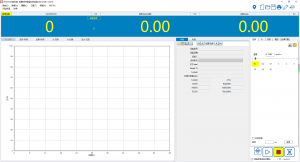
(1) The software can run on the Windows 7 system, and the user interface presents a Chinese window system consistent with the Windows style. All experimental operations can be completed through mouse input on the computer screen.
Main interface of the testing machine
(The software interface is slightly different, mainly based on reality)
7. Test report:
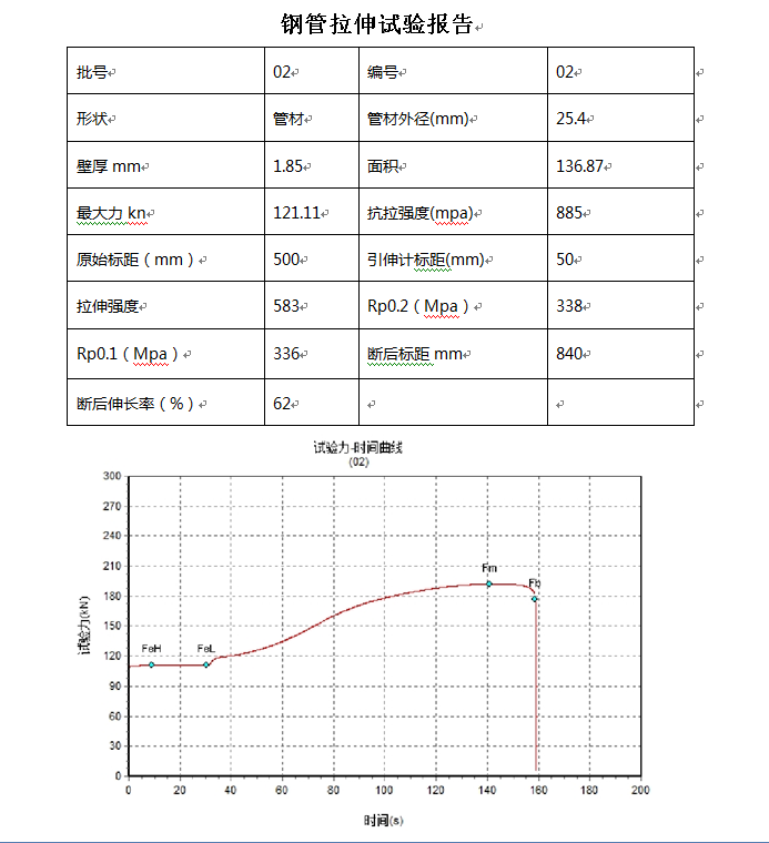
Search and manage experimental data through experimental data files; Customize the content and format of experimental reports through report template settings; By editing formulas and result items, support for the vast majority of experimental standards and methods can be achieved; After loading one or more test data files, generate a test report according to the report template and print it out; Supports Word and Excel report templates, and can be freely edited;
(The data is for reference only and has no practical significance)
8. Safety protection device
(1) When the test force exceeds 2% -5% of the maximum test force, overload protection is activated and the system is unloaded.
(2) When the piston rises to the upper limit position, the stroke protection stops and the oil pump motor stops.
Main performance and technical indicators
|
NO. |
Project Name |
Parameters |
|
1 |
Maximum test force kN |
six hundred |
|
2 |
Host structure |
Four pillars and two lead screws |
|
3 |
Relative error of test force indication |
≤ ± 1% of the indicated value |
|
4 |
Test force measurement range |
2%~100% of maximum test force |
|
5 |
Constant velocity stress control range (N/mm2 · S-1) |
2~60 |
|
6 |
Constant strain control range |
0.00025/s~0.0025/s |
|
7 |
Constant velocity displacement control range (mm/min) |
0.5~50 |
|
8 |
clamping system |
Hydraulic clamping |
|
9 |
Circular specimen clamping diameter range mm |
Choose any set within the range of Φ 6 to Φ 40 |
|
10 |
Flat specimen clamping thickness range mm |
0~15 |
|
11 |
Flat specimen clamping width mm |
seventy |
|
12 |
Maximum tensile test space mm |
550 (size customizable) |
|
13 |
Maximum compression test space mm |
500 (size customizable) |
|
14 |
Control cabinet external dimensions mm |
1100×620×850 |
|
15 |
Host dimensions in millimeters |
900 × 630 × 2300 (size can be customized) |
|
16 |
Motor power kW |
two point three |
|
17 |
Host weight kg |
one thousand and five hundred |
|
18 |
Column center distance (mm) |
four hundred and fifty |
|
19 |
Upper and lower pressure plate size mm |
Φ160 |
|
20 |
Bending support rod spacing mm |
450 (size customizable) |
|
21 |
Bending support rod width mm |
140 (size customizable) |
|
22 |
Allowable bending degree mm |
100 (size customizable) |
|
23 |
Maximum piston stroke mm |
two hundred |
|
24 |
Maximum piston movement speed mm/min |
About 60 |
|
25 |
Experimental space adjustment speed mm/min |
About 150 |
Standard configuration
|
NO. |
Name |
Specifications |
Qty. |
remarks |
|
1 |
host |
|
1 Set |
Self-produced |
|
2 |
Servo controlled oil source |
|
1 Set |
Self-produced |
|
4 |
Control cabinet |
|
1 Set |
Self-produced |
|
5 |
Measurement and Control System |
|
1 Set |
Self-produced |
|
6 |
Wheel spoke sensor |
|
1pcs |
Wide testing |
|
7 |
Stretching encoder |
|
1pcs |
Jinan |
|
8 |
computer |
|
1 Set |
HP |
|
9 |
printer |
|
1 Set |
HP |
|
10 |
Round specimen jaws mm |
Choose any pair within the range of Φ 6- Φ 13, Φ 13- Φ 26, and Φ 26- Φ 40 |
1pcs |
Self-produced
|
|
11 |
Flat sample jaws mm |
0~15 |
1pcs |
|
|
12 |
Compression attachment mm |
Φ150 |
1 Set |
Self-produced |
|
13 |
Oil pump |
|
1 Set |
Mazzic, Italy |
|
14 |
electric machinery |
|
1 Set |
Shanghai Songhui |
|
15 |
Technical documents |
User manual, packing list, certificate of conformity |
1pcs |
Self-produced |
Operating procedures:
Operating procedures for electro-hydraulic servo testing machine
1. Start the computer and enter the software
2. Start the power switch and oil source main switch of the electro-hydraulic servo controller
3. Adjust the center crossbeam of the testing machine host to the appropriate position, and replace the appropriate fixture according to the shape, size, and experimental purpose of the sample
4. Turn on the power switch of the oil pump and lift the oil cylinder of the testing machine to eliminate its own weight. (You can choose a displacement speed of 10mm/min and click the [Up] button to raise the oil cylinder by about 1mm).
5. Enter relevant information about the style in the data version of the software.
6. After clamping the style onto the upper jaw, reset the force value to zero, adjust the middle crossbeam to the appropriate position, clamp the lower jaw, and reset the displacement and deformation. (The style should be clamped to more than 80% of all jaws, and kept vertical and aligned)
7. Choose the appropriate speed or plan, click the 【 Start 】 button in the software, and conduct the experiment
After the sample fractures, the test automatically ends. To view experimental data, click on the data version in the software to view the required data
After the completion of all sample tests, the oil cylinder piston falls to the bottom of the oil cylinder and the oil source main switch is turned off.
8. Exit the operating software, shut down the computer, and turn off the host power.
Attention:
1. The iron shavings in the jaws of the testing machine should be regularly removed to keep the jaws clean
When cleaning equipment and maintaining hygiene in the working environment, the power should be disconnected
During the experiment, if the oil pump suddenly stops working, the applied load should be unloaded, checked, and the oil pump should be restarted
When the testing machine is temporarily suspended, the oil pump motor should be turned off, and the test bench should be lowered after the test is completed. The piston of the oil cylinder should not fall to the bottom of the cylinder and flow out a certain distance to facilitate future use
5. Avoid letting the equipment get damp or come into contact with liquid substances, and prevent the equipment from being shaken or impacted
6. Please do not leave the operating room and press the emergency stop switch in case of an emergency
7. Stay away from magnetic interference
8. Non professional technical personnel are not allowed to modify the software program of the testing machine
Quality Assurance
The company guarantees that all products are produced in accordance with the corresponding national standards;
The company guarantees that all domestic accessories are from well-known brands with excellent quality;
The company guarantees that all foreign accessories are original and genuine products from the factory;
The company guarantees that the products provided to users are brand new original machines;
The company guarantees that all products leaving the factory undergo strict inspection according to procedures;
The company promises to accept customers to visit and supervise the factory at any time.
User preparation conditions
Skilled operators in computer applications;
The user should clarify the test methods and standard details that the experiment refers to and follows;
Provide samples that have been tested on this machine for product testing, factory inspection, and machine adjustment testing;
The space, foundation, power supply, etc. required for product installation;
The laboratory should be equipped with air conditioning, with indoor temperature controlled between 15-25 ℃ and humidity<70%;
Responsible for receiving, storing, and relocating products;
Usage and maintenance
Fixed and trained test personnel must be arranged to operate the product, and others are not allowed to operate it;
When using the product, operators should follow the training and guidance they have received to operate it in the correct procedure;
Operators should be proficient in the corresponding test standards in order to accurately determine the test results;
Operators must carefully read the host manual and software manual;
At the end of the experiment, turn off the machine in the correct order and cut off all power sources;
If self-made test auxiliary fixtures are used, the original structure of the product must not be changed or damaged during installation;
If there is an abnormal situation or electrical failure during the operation of the testing machine, and the start or stop button does not work, the power should be immediately cut off to stop the testing machine from running;
The screw and transmission parts should be regularly coated with lubricating oil to prevent dry friction;
If the product malfunctions, please contact our customer service department in a timely manner and do not disassemble it directly without authorization;
Do not modify the product on your own.

SHANDONG DRICK INSTRUMENTS CO.,LTD
Company Profile
Shandong Drick Instruments Co., Ltd, is mainly engaged in the research and development, manufacturing and sales of testing instruments.
The company established in 2004.
Products are used in scientific research units, quality inspection institutions, universities, packaging, paper, printing, rubber and plastics, chemicals, food, pharmaceuticals, textiles, and other industries.
Drick pays attention to talent cultivation and team building, adhering to the development concept of professionalism, dedication.pragmatism, and innovation.
Adhering to the customer-oriented principle, solve the most urgent and practical needs of customers, and provide first-class solutions to customers with high-quality products and advanced technology.


