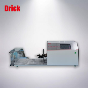
DRK255–Sweating Guarded Hotplate Test Instrument

Short Description:
First of all, thank you very much for purchasing our DRK255 Sweating Guarded Hotplate, before installation and using, please read this manual carefully, which could help you to standardize the operation and make the test results accurate easier. Catalog l Overview 1.1 Brief Introduction 1.2 Application 1.3 Instrument function 1.4 Use environment 1.4.1 Ambient temperature and humidity 1.4.2 Power requirements 1.4.3 No around vibration sources, etc. 1.5 Technical parameters 1.6 Principle Introd...
First of all, thank you very much for purchasing our DRK255 Sweating Guarded Hotplate, before installation and using, please read this manual carefully, which could help you to standardize the operation and make the test results accurate easier.
Catalog
l Overview
1.1 Brief Introduction
1.2 Application
1.3 Instrument function
1.4 Use environment
1.4.1 Ambient temperature and humidity
1.4.2 Power requirements
1.4.3 No around vibration sources, etc.
1.5 Technical parameters
1.6 Principle Introduction
1.6.1 Definition and unit of thermal resistance
1.6.2 Definition and unit of moisture resistance
1.7 Instrument structure
1.8 Instrument characteristics
1.8.1 Low repeatability error
1.8.2 Compact structure and strong integrity
1.8.3 Real-time display of “thermal and humidity resistance” values
1.8.4 Highly simulated skin-sweating effect
1.8.5 Multi-point independent calibration
1.8.6 Microclimate temperature and humidity are consistent with standard control points
l Before Using
2.1 Acceptance and inspection
2.2 Installation
2.3 Turn on the power and verify
l Operation
3.1 Test methods and standards
3.2 Preparation before starting
3.3 Run thermal resistance operation
3.3.1 Machine preheating
3.3.2 Thermal resistance setting
3.3.3 Thermal resistance blank plate test
3.3.4 Thermal resistance test
3.3.5 View, print and delete thermal resistance
3.3.6 Thermal resistance calibration
3.3.7 Thermal resistance applicable samples
3.4 Run moisture resistance operation
3.4.1 Machine preheating
3.4.2 Moisture resistance setting
3.4.3 Humidification and water replenishment operation
3.4.4 Moisture resistance blank plate test
3.4.5 Moisture resistance test
3.4.6 Viewing and printing moisture resistance
3.4.7 Moisture resistance calibration
3.4.8 Moisture resistance applicable samples
3.4.9 Conversion of moisture resistance and thermal resistance test
l Sample requirements
4.1 Sample humidity control
4.2 Sample quantity and size
4.3 Requirements for sample placement
l Significance of thermal and moisture resistance
5.1 The significance of thermal resistance
5.2 The significance of moisture resistance
l Technical support
6.1 Fault identification
6.2 Maintenance
l Common problems
7.1 The problem of detection time
7.2 The problem of sample size
7.3 Whether the setting temperature is related to the thermal resistance value
7.4 Detected index problem
7.5 Calibration of the instrument and standard sample problems
l 8. Appendix: Test reference time
Overview
1.1 Overview of the manual
The manual provides the DRK255 Sweating Guarded Hotplate application, basic detection principles and detailed using methods, gives the instrument indicators and accuracy ranges, and describes some common problems and treatment methods or suggestions.
1.2 Scope of application
DRK255 Sweating Guarded Hotplate is suitable for different kinds of textile fabrics, including industrial fabrics, non-woven fabrics and various other flat materials.
1.3 Instrument function
This is an instrument used to measure the thermal resistance (Rct) and moisture resistance (Ret) of textiles (and other) flat materials. This instrument is used to meet the ISO 11092, ASTM F 1868 and GB/T11048-2008 standards.
1.4 Use environment
The instrument should be placed with relatively stable temperature and humidity, or in a room with general air-conditioning. Of course, it would be best in a constant temperature and humidity room. The left and right sides of the instrument should be left at least 50cm to make the air flow in and out smoothly.
1.4.1 Environmental temperature and humidity:
Ambient temperature: 10℃ to 30℃; Relative humidity: 30% to 80%, which is conducive to the stability of temperature and humidity in the microclimate chamber.
1.4.2 Power requirements:
The instrument must be well grounded!
AC220V±10% 3300W 50Hz, the maximum through current is 15A. The socket at the power supply place should be able to withstand more than 15A current.
1.4.3 There is no vibration source around, no corrosive medium, and no penetrating air circulation.
1.5 Technical Parameter
1. Thermal resistance test range: 0-2000×10-3 (m2 •K/W)
The repeatability error is less than: ±2.5% (factory control is within ±2.0%)
(The relevant standard is within ±7.0%)
Resolution: 0.1×10⁻³ (m2 •K/W)
2. Moisture resistance test range: 0-700 (m2 •Pa / W)
The repeatability error is less than: ±2.5% (factory control is within ±2.0%)
(The relevant standard is within ±7.0%)
3. Temperature adjustment range of test board: 20-40℃
4. The speed of the air above the surface of the sample: Standard setting 1m/s (adjustable)
5. Lifting range of the platform (sample thickness): 0-70mm
6. Test time setting range: 0-9999s
7. Temperature control accuracy: ±0.1℃
8. Resolution of temperature indication: 0.1℃
9. Pre-heat period: 6-99
10. Sample size: 350mm×350mm
11. Test board size: 200mm×200mm
12. External Dimension: 1050mm×1950mm×850mm (L×W×H)
13. Power supply: AC220V±10% 3300W 50Hz
1.6 Principle Introduction
1.6.1 Definition and unit of thermal resistance
Thermal resistance: the dry heat flow through a specified area when the textile is in a stable temperature gradient.
The thermal resistance unit Rct is in Kelvin per watt per square meter (m2·K/W).
When detecting the thermal resistance, the sample is covered on the electric heating test board, the test board and the surrounding protection board and the bottom plate are kept at the same set temperature (such as 35℃) by electric heating control, and the temperature sensor transmits the data to the control system to maintain a constant temperature, so that the heat of the sample plate can only be dissipated upward (in the direction of the sample), and all other directions are isothermal, without energy exchange. At 15mm on the upper surface of the center of the sample, the control temperature is 20°C, the relative humidity is 65%, and the horizontal wind speed is 1m/s. When the test conditions are stable, the system will automatically determine the heating power required for the test board to maintain a constant temperature.
The thermal resistance value is equal to the thermal resistance of the sample (15mm air, test plate, sample) minus the thermal resistance of the empty plate (15mm air, test plate).
The instrument automatically calculates: thermal resistance, heat transfer coefficient, Clo value and heat preservation rate
Note: (Because the repeatability data of the instrument is very consistent, the thermal resistance of the blank board only needs to be done once every three months or half a year).
Thermal resistance: Rct: (m2·K/W)
Tm ——testing board temperature
Ta ——testing cover temperature
A —— testing board area
Rct0——blank board thermal resistance
H —— testing board electric power
△Hc— heating power correction
Heat transfer coefficient: U =1/ Rct (W /m2·K)
Clo:CLO= 1 0.155·U
Heat preservation rate: Q=Q1-Q2 Q1×100%
Q1-No sample heat dissipation(W/℃)
Q2-With sample heat dissipation(W/℃)
Note: (Clo value: at a room temperature of 21℃, relative humidity ≤50%, airflow 10cm/s (no wind), the test wearer sits still, and its basal metabolism is 58.15 W/m2 (50kcal/m2·h), feel comfortable and maintain the average temperature of the body surface at 33℃, the insulation value of the clothes worn at this time is 1 Clo value (1 CLO=0.155℃·m2/W)
1.6.2 Definition and unit of moisture resistance
Moisture resistance: the heat flow of evaporation through a certain area under the condition of a stable water vapor pressure gradient.
The moisture resistance unit Ret is in Pascal per watt per square meter (m2·Pa/W).
The test plate and the protection plate are both metal special porous plates, which are covered with a thin film (which can only permeate water vapor but not liquid water). Under the electric heating, the temperature of the distilled water provided by the water supply system rises to the set value (such as 35℃). The test board and its surrounding protection board and bottom plate are all maintained at the same set temperature (such as 35°C) by electric heating control, and the temperature sensor transmits the data to the control system to maintain a constant temperature. Therefore, the water vapor heat energy of the sample board can only be upwards (in the direction of the sample). There is no water vapor and heat exchange in other directions,
the test board and its surrounding protection board and bottom plate are all maintained at the same set temperature (such as 35°C) by means of electric heating, and the temperature sensor transmits the data to the control system to maintain a constant temperature. The water vapor heat energy of the sample plate can only be dissipated upward (in the direction of the specimen). There is no water vapor heat energy exchange in other directions. The temperature at 15mm above the specimen is controlled at 35℃, the relative humidity is 40%, and the horizontal wind speed is 1m/s. The lower surface of the film has a saturated water pressure of 5620 Pa at 35℃, and the upper surface of the sample has a water pressure of 2250 Pa at 35℃ and a relative humidity of 40%. After the test conditions are stable, the system will automatically determine the heating power required for the test board to maintain a constant temperature.
The moisture resistance value is equal to the moisture resistance of the sample (15mm air, test board, sample) minus the moisture resistance of the empty board (15mm air, test board).
The instrument automatically calculates: moisture resistance, moisture permeability index, and moisture permeability.
Note: (Because the repeatability data of the instrument is very consistent, the thermal resistance of the blank board only needs to be done once every three months or half a year).
Moisture resistance: Ret Pm——Saturated vapor pressure
Pa——Climate chamber water vapor pressure
H——Test board electric power
△He—Correction amount of test board electric power
Moisture permeability index: imt=s*Rct/Ret S— 60 pa/k
Moisture permeability: Wd=1/( Ret *φTm) g/(m2*h*pa)
φTm—Latent heat of surface water vapor, when Tm is 35℃时,φTm=0.627 W*h/g
1.7 Instrument structure
The instrument is composed of three parts: the main machine, microclimate system, display and control.
1.7.1 The main body is equipped with a sample plate, a protection plate, and a bottom plate. And each heating plate is separated by a heat insulating material to ensure no heat transfer between each other. In order to protect the sample from the surrounding air, a microclimate cover is installed. There is a transparent organic glass door on the top, and the temperature and humidity sensor of the test chamber is installed on the cover.
1.7.2 Display and prevention system
The instrument adopts the weinview touch display integrated screen, and controls the microclimate system and the test host to work and stop by touching the corresponding buttons on the display screen, input control data, and output test data of the test process and results
1.8 Instrument characteristics
1.8.1 Low repeatability error
The core part of DRK255 the heating control system is a special device independently researched and developed. Theoretically, it eliminates the instability of the test results caused by thermal inertia. This technology makes the error of the repeatable test far smaller than the relevant standards at home and abroad. Most of the “heat transfer performance” test instruments have a repeatability error of about ±5%, and our company has reached ±2%. It can be said that it has solved the long-term world problem of large repeatability errors in thermal insulation instruments and reached the international advanced level. .
1.8.2 Compact structure and strong integrity
The DRK255 is a device that integrates the host and the microclimate. It can be used independently without any external devices. It is adaptable to the environment and specially developed to reduce the use conditions.
1.8.3 Real-time display of “thermal and humidity resistance” values
After the sample is preheated to the end, the entire “thermal heat and moisture resistance” value stabilization process can be displayed in real time. This solves the problem of the long time for the heat and moisture resistance experiment and the inability to understand the entire process.
1.8.4 Highly simulated skin-sweating effect
The instrument has a high simulation of human skin (hidden) sweating effect, which is different from the test board with only a few small holes. It satisfies the equal water vapor pressure everywhere on the test board, and the effective test area is accurate, so that the measured “moisture resistance” is closer real value.
1.8.5 Multi-point independent calibration
Due to the large range of thermal and moisture resistance testing, multi-point independent calibration can effectively improve the error caused by nonlinearity and ensure the accuracy of the test.
1.8.6 Microclimate temperature and humidity are consistent with standard control points
Compared with similar instruments, adopting the microclimate temperature and humidity consistent with the standard control point is more in line with the “method standard”, and the requirements for microclimate control are higher.
Before Using
The description of the content in this section includes a quick start summary to help you understand faster. This will guide you through the setup, calibration and basic operation of the instrument. It is recommended that you start studying this part after browsing the previous content.
2.1 Acceptance and inspection
Open the box and take out the whole machine to check for obvious damage.
Count according to the packing list, operating instructions and accessories.
2.2 Installation
2.2.1 Adjust the four feet to center the built-in horizontal bubble to ensure the level of the test board.
2.2.2 Wiring
Connect one end of the computer cable to the computer socket of the instrument and one end to the computer (optional)
2.3 Turn on the power and verify
Turn on the power and observe whether the display is normal.
Operation
3.1 Test methods and standards
ISO 11092, ASTM F 1868, GB/T11048-2008
3.2 Preparation before starting
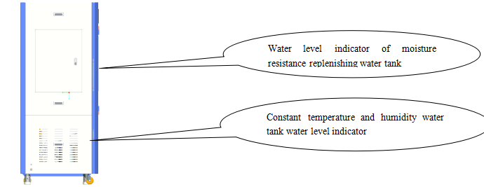
3.2.1 Before starting the machine, check whether there is enough water in the water level indicator of the constant temperature and humidity water tank. If there is no water, please add water first. Otherwise, even if it is turned on, the constant temperature and humidity will not work. How to add water: Open the front door, unscrew the stainless steel cover on the left, take the accessory funnel, and pour mineral water (distilled water is recommended) to provide microclimate humidity adjustment. Pour the water to between the water level indicator lines.
3.2.2 Please confirm whether there is water in the water level indicator of the moisture resistance replenishing water tank on the upper left side, and then supply the moisture resistance test. Operation method: refer to item 3.4.3 [Humidification and replenishment operation and test film placement operation] Note: This water tank must be filled with distilled water.
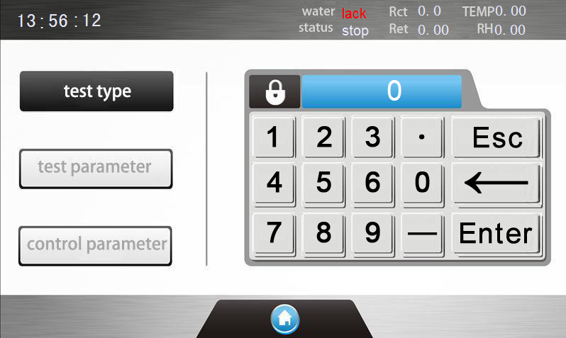
3.2.3 Page introduction and parameter setting
Constant temperature and humidity setting; after turning on the power, the following login interface is displayed:
Click the “Login” button to enter the password

After input the correct, it will shows:
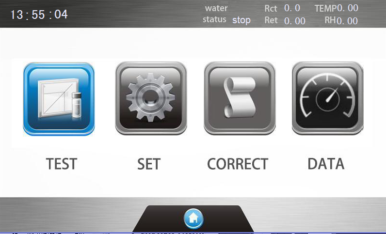
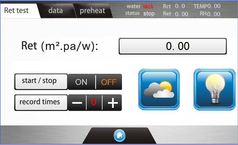
The main interface has 4 items: test, set, correct and data.
Test: The test interface is used to enter the thermal resistance or moisture resistance experiment, and to turn on or off the refrigeration system and lighting.

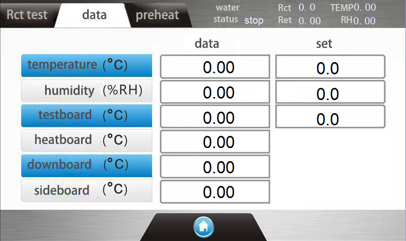
Press the refrigeration control button in Figure 305-1 to turn on or off the refrigeration and start the constant temperature and humidity system and control the lighting; Figure 305-2 equipment real-time operating data; Figure 305-3 is the cold machine preheating function;
Setting: it is used to set the test parameters and the temperature and humidity climate environment parameters
Temperature and humidity parameter settings:
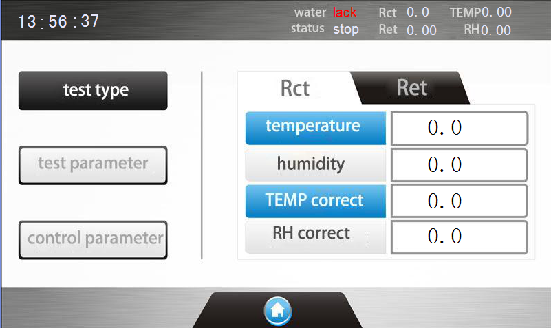
When selecting thermal resistance, the system will automatically set the microclimate temperature to 20℃ and humidity to 65%;
When selecting moisture resistance, the system will automatically set the microclimate temperature to 35°C and humidity to 40%;
Users can also set other temperature and humidity parameters according to actual conditions.
Temperature and humidity control parameter settings in the warehouse:
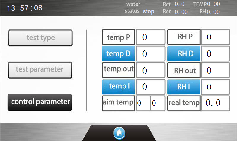
Temperature and humidity control parameter setting interface, this part of the parameter has been set before leaving the factory, the user generally does not need to set this item, if necessary, the factory professional can set it.
Thermal and moisture resistance parameter setting:
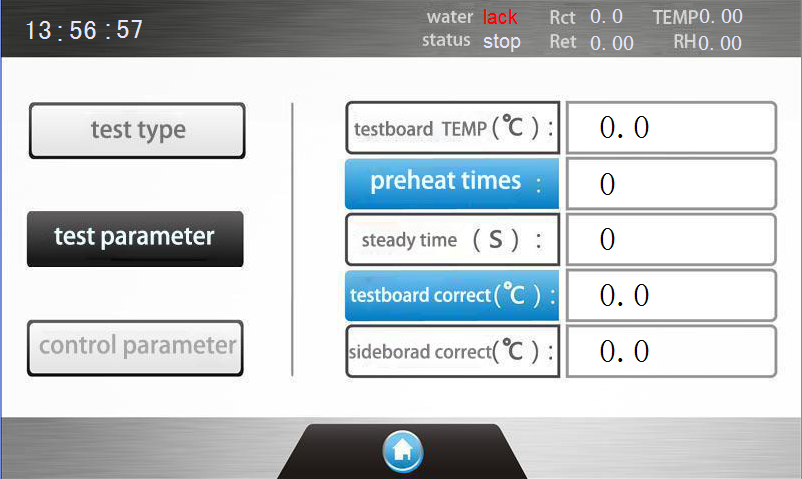
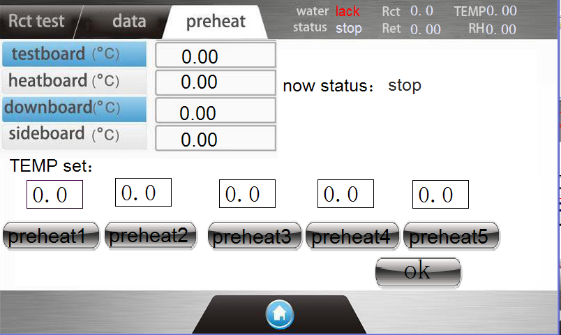
According to the standard, the temperature of the test board is set to 35℃, the preheating cycle is generally 6 times, and the test time is 600 seconds (this is the conventional default setting, such as the first test of the sample or the test of a thicker sample. testing time).
Print: used to query and print out data, and delete records
Rct Correct: used to calibrate the thermal resistance data
3.3 Run thermal resistance operation
First check whether the test board is completely dry (if wet, please refer to 3.4.9 operation).
3.3.1 Machine preheating
After turning on the power, the whole machine needs to be preheated for about 45 minutes, during which a medium-thickness fabric is placed on the perforated plate. When the test plate reaches 35°C, the fabric is taken out, and then the temperature of the heating plate and the bottom plate are observed to reach about 35.2 to complete the cooling. After the machine is preheated, the test sample (or standard sample) can be put into the test bench.
3.3.2 Thermal resistance setting See Figure 309
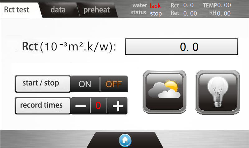
Set the parameters in the parameter setting and press “Test” to enter the “thermal resistanc” test
The test interface displays as shown in Figure 314:

3.3.3 Thermal resistance blank plate test
Before testing, there must be “no sample thermal resistance”- blank plate thermal resistance.
The thermal resistance of the blank plate is the thermal resistance of the instrument itself without the sample.
In the “thermal resistance operation” interface, select “test times” to 0 and press “start” to do the “thermal resistance blank plate test”. Test sequence: preheat-stable-test-stop (obtain the thermal resistance of the blank board and automatically store it)
Note: “Blank board thermal resistance” is recommended to be done once in March to June. Because the repeatability error of the empty board test of this instrument is quite small, it is not necessary to start the blank board thermal resistance every day.
3.3.4 Thermal resistance test
In the “thermal resistance operation” interface

After meet the 3.3.1 request, put the sample on the surface of the perforated plate, adjust the “up and down” button on the front of the test bench inside the test chamber, and cover the four sides of the metal holder, when the metal holder is exactly in the horizontal position. Put down the plexiglass cover, close the door of the instrument, press the “start” button, and the instrument will run automatically.
The running sequence: preheat-stable-test-stop, display the first thermal resistance and other indicators.
Note: After displaying “stable”, if the user thinks that the data is credible and does not need to continue testing, you can press the “stop” button, and the instrument will retain the displayed thermal resistance value as the test result.
Change the sample, press 2 for the “record times” to test the second sample, and so on. The test report can be printed after 3 tests according to the method standard.
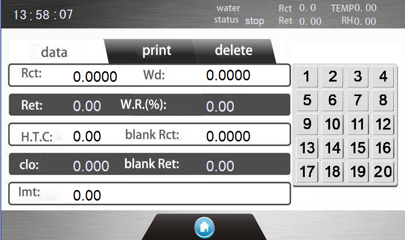
3.3.5 View, print and delete thermal resistance
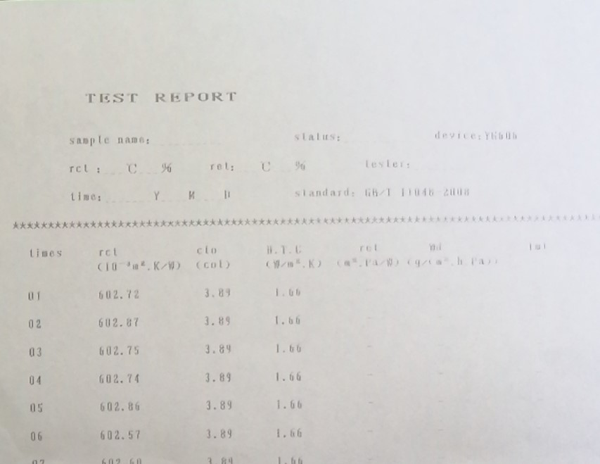
Press “Print” to display the “Data Query and Print” interface, as shown in Figure 317
Press the “OK” button again, and the instrument will automatically print the thermal resistance test report, as shown in Figure 318.
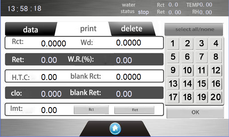
Switch to the delete interface, select the record to be deleted, and then press “OK”, the currently selected test data will be deleted, and its position will be replaced by the next test data.
3.3.6 Thermal resistance calibration
It is recommended to do this when a new machine, or calibrated once every six months, and when the value is abnormal.
3.3.6.1 Put the sponge standard sample (standard sample with nominal thermal resistance value) provided in the instrument accessories in the test bench
3.3.6.2 Check the test results and standard results under the thermal resistance calibration page to ensure that all data are zero.
3.3.6.3 In the thermal resistance test interface, select “record time 1” and press the “Start” button. Note: You also need to meet the 3.3.1 clause before pressing the “Start” button.
During the thermal resistance test, the upper right corner of the same page first displays “Preheat”, “Stable”, “Test”, “Stop”, and “record time 1”, end of the test.
3.3.6.4 Then put in the sponge standard samples of other thicknesses, and measure the test results of “record time 12” and “record time 3” as in 3.3.6.1 to 3.3.6.3.
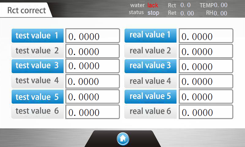
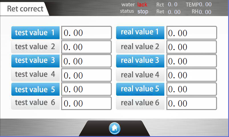
3.3.6.5 Input the measured thermal resistance values of sponge standard samples of different thicknesses into the corresponding items of “Test Results”, and input the “standard data values” on the corresponding standard samples into the corresponding items of ”Standard Result” .

The user can also select only one or two thickness standards for calibration, and input "0" for the rest. Note: In the "Thermal Resistance Calibration" interface, enter the measured sponge standard sample data from small to large in order of test results 1, 2, 3, and standard results 1, 2, 3.
Press "Return" to exit the interface and the calibration is complete.
Note: Do not change the data in the thermal resistance calibration easily at ordinary times. It is best to keep a copy in other places to avoid losing the calibration data.
The user can also select only one or two thickness standards for calibration, and input “0” for the rest. Note: In the “Thermal Resistance Calibration” interface, enter the measured sponge standard sample data from small to large in order of test results 1, 2, 3, and standard results 1, 2, 3.
Press “Return” to exit the interface and the calibration is complete.
Note: Do not change the data in the thermal resistance calibration easily at ordinary times. It is best to keep a copy in other places to avoid losing the calibration data.
3.3.7 Thermal resistance applicable samples
This instrument is not limited to the thermal resistance detection of textiles, and can be applied to the thermal resistance detection of various plate materials.
3.4 Run moisture resistance operation
3.4.1 Machine preheating
After turning on the power, the whole machine needs to be preheated for about 60 minutes. During the period, it should be ensured that the 3.4.3 humidification and water replenishment operation and the test film placement operation have been completed. Put a medium-thickness fabric on the porous plate, and take the fabric out when the test plate reaches 35℃ , And then observe the heating plate temperature and the bottom plate temperature to about 35.2, complete the cold machine preheating, you can put the test sample into the test bench.
3.4.2 Moisture resistance setting
Press the “Settings” button, and press “Heat and Humidity Resistance Parameter Setting” to display the 309 interface.
3.4.3 Humidification and water replenishment operation
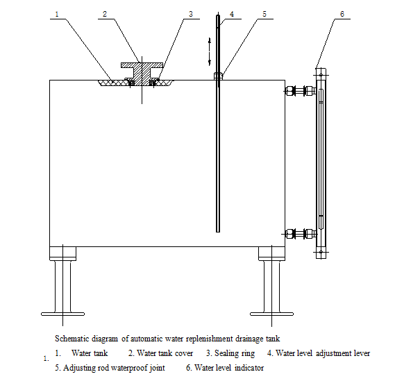
Check whether there is water in the automatic water-replenishing tank. If there is no water, open the small door on the left side of the instrument, unscrew the water tank cover 2, theninsert the water level indicator rod 4 into the bottom of the water tank and tighten the adjusting rod waterproof nut 5, and take the funnel from the accessories, Then pour distilled water into the mouth of the water tank, make the water level between the red lines of the water level indicator 6, and then tighten the water tank lid.
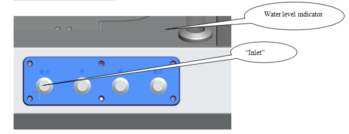
Press the “Water Inlet” button shown in Figure 323, loosen the waterproof connector of the adjusting rod a little, and slowly pull up the water level adjusting rod. The water in the replenishing tank will automatically flow into the test body. Observe the water level indicator on the right side of the test bench and test If you touch the surface of the porous plate with your hand, when moisture comes out, you can stop the water level adjustment lever to pull up, and tighten the waterproof connector.
Test film placement: Take a test film from the attachment, tear off the protective film, and use the elastic one for testing. Spread it on the surface of the porous plate. Take the cotton block in the attachment to smooth the film and smooth the film. Remove the air bubbles between the plates, and then take the rubber strip from the attachment, and fix the film on the test body in the circumferential direction.
3.4.4 Moisture resistance blank plate test
Before the instrument detects the sample, there must be “no sample moisture resistance”-the blank board wet resistance.
The moisture resistance of the blank plate refers to the moisture resistance of the instrument itself when there is only a film.
Select “record time 0” and press “Start” to do “blank board moisture resistance” test.
Moisture resistance test process: preheat-stable-test-stop (obtain the moisture resistance of the empty board and automatically store it)
3.4.5 Moisture resistance test
In the humidity resistance operation interface (can be carried out after the temperature of the three plates reaches the 3.4.1 clause)
Select 1 for the record time (ie, sample 1).
After the instrument meets the requirements of 3.4.1, place the test sample on the upper surface of the film, press the "up, down" button, and cover the four sides of the metal crimp. When the metal crimp is in the horizontal position, then put down the plexiglass cover. Close the door of the instrument and press the "Start" button. The instrument will run automatically. The running sequence is: warm-up-stability-test-stop, and display the first moisture resistance and other indicators.
Change the sample; press 2 for the record time to test the second sample, the method is the same as above, and so on. The moisture resistance test report can be printed after 3 tests according to the method standard.
3.4.6 Viewing and printing moisture resistance
Moisture resistance needs to be calibrated. The steps are similar to thermal resistance calibratuion.
3.4.7 Moisture resistance applicable samples
This instrument is not limited to the moisture resistance detection of textiles, it is also suitable for the moisture resistance detection of various plate materials, but it is meaningless to detect the moisture resistance of impermeable objects, because the value of the moisture resistance is infinite.
3.4.8 Conversion of moisture resistance and thermal resistance test
On the left side of the instrument, as shown in Figure 327, connect the compressed air, place a drain pan under the drain, and then press the “Drain” button inside the test chamber as shown in Figure 317, generally press 6 About 8 times (one time after hearing a “click”), the water will be discharged automatically, and then set the temperature of the test board to 40℃, and run for 1 hour (after that, if the test board and the protection board are still If there is moisture, the time can be extended appropriately). When doing this operation, there should be no sample or moisture resistance test film on the test surface.
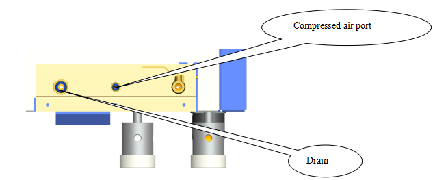
l Compressed air port
4.1 Sample humidity control: the samples and test samples should be placed under the specified standard atmospheric conditions for humidity control for 24 hours.
4.2 Sample quantity and size: Take three samples for each sample, the size of the sample is 35×35cm, and the sample should be flat and free of wrinkles.
4.3 Requirements for sample placement: The front side of the sample is laid flat on the test board, and all the sides of the test board are covered.
l Significance of thermal and moisture resistance
5.1 Thermal resistance is a characterization of the heat transfer performance of materials. It is one of the most basic indicators for testing textiles. Because of the three basic functions of clothing (warmth preservation, body protection and self-expression), the most important thing is to keep warm. If there is no clothing today The protection of human beings cannot survive. Secondly, different regions and seasons have different thermal requirements. Thermal resistance can provide a basis for people to choose what kind of fabric, which shows the importance of detecting thermal resistance.
5.2 Moisture resistance is an indicator that reflects the ability of materials to transmit moisture. With the improvement of people's living standards, higher requirements are put forward for wearing comfort, because an adult will pass through the skin even if there is no sweat (significant sweat) every day The capillary discharges water vapor (called hidden sweat), 30-70 g/day*person. Then most of these moisture needs to be transmitted through clothing. Only when the ability of the clothing material to transmit moisture exceeds this value can people feel comfortable. For this reason, it is more important to detect moisture resistance.
l Technical support
6.1 Fault identification
A、 No display on the boot screen
- Check whether the power is on
- Check whether the power of the display is connected
- Check whether the power of the display is connected
B、 Constant temperature and humidity cannot run
- The water level in the boot interface is yellow, please add water
- Check whether the connection line between the control board and the drive board is well connected
- Check whether the pressure of the refrigeration compressor is higher or lower than the set pressure
C、Constant temperature and humidity operation, low test chamber temperature
- Check whether the air heating tube can be heated normally;
- Check the solid state relay driving the air heating tube.
D、 Temperature and humidity operation, low humidity in the test chamber
- Check whether the heating pipe of the water tank can be heated normally
- Check the solid state relay that drives the heating pipe of the water tank
E、 No temperature display on test board, heating board or bottom
1. Whether the temperature sensor is burned out
2. The contact of the connector is not good, plug it in again.
F、The test board, heating board or bottom plate can not heat up or heat up slowly
1. Check whether the three switching power supplies are normally supplied with power;
2. Check the control circuit of the heater to see if there is a bad contact with the indirect plug.
6.2 Maintenance
A. Do not collide with various parts during the transportation, installation, adjustment and use of the instrument to avoid mechanical damage and affect the test results.
B. The control panel of the instrument is a liquid crystal and touch screen, which are easily damaged parts. Do not use other hard objects to replace your fingers during operation. Do not drip organic solvents on the touch screen to avoid shortening the service life.
C. Do a good job of dust-proof treatment after each use of the instrument and clean up the dust in time.
D. When the instrument malfunctions, please ask a professional for repair or repair under the guidance of a professional.
l Common problems
7.1 The question of detection time
Detection time is a matter of great concern to everyone, and I always hope to be fast and accurate. Since the previous standard stipulates the ratio of the five cycles of power-on and power-off time for any sample after 30 minutes of preheating to calculate the result, it is about less than an hour to test one data. There is such a preconceived concept that I always feel that the current test time Too long. The preheating time in the current method standard emphasizes the need to reach a steady state, rather than the previous fixed time. This is for a reason. Because the thermal resistance range of textiles is large, it needs to reach 35°C on one side and 20°C on the other side. The time required for steady state is different. For example, it takes at least 2 hours for coats to reach steady state, while down jackets take longer. On the other hand, most textiles absorb moisture. Although the sample has been adjusted and balanced in advance, the state of the test has changed. The temperature of the former is 20℃ and the humidity is 65%, while the latter is 35℃ on one side and 20℃ on the other. The moisture regain of the sample after the balance also changes. We did a comparative test. The weight of the former of the same sample is greater than the former. Everyone knows that it takes a long time to rebalance the moisture regain of textiles. Therefore, the time for detecting thermal resistance cannot be short.
It also takes a long time for the sample to reach the isothermal and unequal water pressure during the moisture resistance test.
The same is true for the time required for similar foreign instruments to detect “thermal and moisture resistance”, please refer to the appendix.
7.2 The question of sample size
The size of the sample is always better. It is not the case in the thermal resistance test. It is correct only from the representative of the sample, but the opposite conclusion can be drawn from the instrument. The size of the test board is larger and the heating is Uniformity is a problem. The new standard requires a wind speed of 1m/s. The larger the size, the greater the speed difference between the air inlet and the air outlet, and the increase in the temperature of the air inlet and the temperature of the air outlet. From the development of standards at home and abroad, we can see that the old standard is mostly 250mm2 and the new standard is 200mm2. Japanese KES uses 100mm2. Therefore, we believe that 200 mm2 is more appropriate for the effective area under the premise of meeting the method standards.
7.3 Whether the setting temperature is related to the thermal resistance value
Generally speaking, the setting temperature has no relation to the thermal resistance value.
The thermal resistance value is related to the area of the sample, the temperature difference between the two sides, and the power required to maintain the steady state.
Rct 
Once the area of the test board is determined, its size should not change. As long as the temperature at both ends is constant, it is not difficult to measure the power required to maintain the constant. It can be seen that the temperature used is irrelevant, as long as the temperature used does not change the properties of the measured object. can. Of course we respect the standard and adopt 35℃.
7.4 Detected index problem
Why does the new standard abolish heat preservation rate and adopt the index of thermal resistance? We can know from the original heat preservation rate formula:
Q1-No sample heat dissipation(W/℃)
Q2-with sample heat dissipation(W/℃)
With the improvement of thermal performance, Q2 decreases linearly, but the thermal insulation rate Q rises very slowly. In actual use, the thermal insulation rate of two-layer coat and one-layer coat is only increased a little, not doubled. This is a formula design Therefore, it is reasonable to abolish this indicator internationally. Secondly, the thermal resistance is very convenient to use, and the value is linearly added. For example, the first coat is 0.085 m2·K/W, and the second floor is 0.170 m2·K/W.
The relationship between thermal resistance and insulation rate:
Rct=A/Q2—Rct0 A:testing area
According to the formula, the thermal resistance changes according to the change of Q2.
The following examples of thermal resistance test data:
|
Test times |
1 |
2 |
3 |
4 |
5 |
Blank thermal |
|
Thermal resistance data(10-3m2·K/W) |
32 |
66 |
92 |
125 |
150 |
58 |
A is 0.04m2 and the Q2would be:
|
Test times |
1 |
2 |
3 |
4 |
5 |
Thermal resistance data |
|
Thermal resistance data 10-3m2·K/W) |
32 |
66 |
92 |
125 |
150 |
58 |
|
Q2(W/℃) |
0.4444 |
0.3226 |
0.2667 |
0.2186 |
0.1923 |
|
Q1 is No sample heat dissipation, Q1 =A/Rct0=0.04/58*1000=0.6897
|
Test times |
1 |
2 |
3 |
4 |
5 |
Thermal resistance data |
|
Thermal resistance(10-3m2·K/W) |
32 |
66 |
92 |
125 |
150 |
58 |
|
Q2(W/℃) |
0.4444 |
0.3226 |
0.2667 |
0.2186 |
0.1923 |
|
|
Insulation rate(%) |
35.57 |
53.22 |
61.33 |
68.31 |
72.12 |
|
According to the data, the curve diagram of thermal resistance and insulation rate:
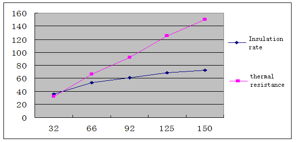
t can be seen from this that as the thermal resistance becomes larger, the warmth retention rate tends to be flat, that is, when the thermal resistance is large, the warmth retention rate is difficult to reflect that it is really big.
7.5 Calibration of the instrument and standard sample problems
The verification of thermal and moisture resistance instruments has become a major problem. If the temperature of the bottom plate is to be measured, it cannot be detected because the instrument is sealed. There are too many factors that affect the test results. The previous verification methods are complicated and have not solved the problem. It is well known that the fluctuation of the test results of the thermal insulation instrument is an indisputable fact. According to our long-term exploration, we believe that the "standard sample" is used to verify the "thermal resistance meter" "It is convenient and scientific.
There are two types of standard samples. One is to use textiles (chemical fiber plain weave), and the other is sponge.
Although textiles are not specified in domestic and foreign standards, the multi-layer superposition method is clearly used to calibrate the instrument.
After our research, we believe that it is not reasonable to use the superposition method, especially the textile superimposition. Everyone knows that after the textile is superimposed, there are gaps in the middle, and there is still air in the gap. The thermal resistance of static air is more than twice the thermal resistance of any textile. The size of the gap is larger than the thickness of the textile, which means that the thermal resistance generated by the gap is not small. Besides, the overlap gap is different for each test, which is difficult to correct, resulting in non-linear stacking of standard samples.
The sponge does not have the above problems. The standard samples with different thermal resistances are integral, not superimposed, such as 5mm, 10mm, 20mm, etc. Of course, the material used is cut off as a whole, which can be considered as homogeneous (now the sponge is uniform Sex is good) To explain that the bubbles in the sponge are homogeneous, the above refers to the additional gap between the layers.
After a lot of experiments, sponge is a very convenient and practical material. It is recommended that the standard focal unit adopt it.
Appendix
Test reference time
|
Sample variety |
Thermal resistance time (min) |
Moisture resistance time (min) |
|
Thin fabric |
About 40~50 |
About 50~60 |
|
Medium fabric |
About 50~60 |
About 60~80 |
|
Thick fabric |
About 60~80 |
About 80~110 |
Note: The above test time is approximately equivalent to similar instruments in the world

SHANDONG DRICK INSTRUMENTS CO.,LTD
Company Profile
Shandong Drick Instruments Co., Ltd, is mainly engaged in the research and development, manufacturing and sales of testing instruments.
The company established in 2004.
Products are used in scientific research units, quality inspection institutions, universities, packaging, paper, printing, rubber and plastics, chemicals, food, pharmaceuticals, textiles, and other industries.
Drick pays attention to talent cultivation and team building, adhering to the development concept of professionalism, dedication.pragmatism, and innovation.
Adhering to the customer-oriented principle, solve the most urgent and practical needs of customers, and provide first-class solutions to customers with high-quality products and advanced technology.